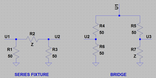
- isn't it starting to look like a series fixture?
- since we know V1, is it necessary to measure Vin?
Antenna analyser
-
- Posts: 799
- Joined: Sat May 23, 2015 5:22 pm
Re: Antenna analyser
Two questions:
-
- Posts: 799
- Joined: Sat May 23, 2015 5:22 pm
Re: Antenna analyser
Sorry if I'm late to comment on the following questions.
Single bridge branch and series fixture look like equivalent circuits. What I still don't understand is what is the advantage of bridge over series fixture?
I think that this kind of bridge was designed for devices with only one input. In case of Red Pitaya, if we can accurately measure both branches of the bridge then the common mode rejection can be done numerically.fisafisa wrote:Instead of using a bridge with a transformer/common mode rejection circuit,
why not simply acquire both branches of the bridge using the 2 RPI inputs?
In my VNA configuration, three series of values are recorded synchronously: DAC samples, ADC1 samples and ADC2 samples. With the open/short/load calibration, there is enough information to calculate Z from the DAC samples and ADC1 samples.fisafisa wrote: One will simply be 0.5 Vin
The other will be Vin /(50 + Z) * Z.
By looking at the phase and amplitude one can measure Z.
In fact, if one could rely on the Zout of RPI, one would not need to measure Vin...
Single bridge branch and series fixture look like equivalent circuits. What I still don't understand is what is the advantage of bridge over series fixture?
The complicated bridge is not the only possible configuration. There are at least four possible configurations:fisafisa wrote:In that case one could duplicate the circuit and make a 2 port measurement.
Just a silly idea, but I cannot be convinced we need a complicated bridge since we have 2 ports?
- shunt fixture
- series fixture
- bridge
- directional coupler
-
- Posts: 20
- Joined: Fri May 29, 2015 11:47 am
- Location: Germany, Elsterberg
Re: Antenna analyser
Hello all,
to use the famous VNA program from pavel for measurements of my symmetrical dipole feed I used the following little circuit:
This configuration gives me good results in the 160m to 10m area. The BNC connector let me plug in a Short (0 Ohms) or Load (50 Ohms) resistor for the calibration.
73, Wolfgang (DH1AKF)
-
- Posts: 1
- Joined: Mon Aug 15, 2016 3:23 pm
Re: Antenna analyser
Following this topic I found it difficult to learn what is the final recommendation for using RP as antenna analyser?
Are two T-links with 50 ohm termination on one side and probes on the other side enough or should we build something else?
73
Simon, S53ZO
Are two T-links with 50 ohm termination on one side and probes on the other side enough or should we build something else?
73
Simon, S53ZO
-
- Posts: 34
- Joined: Fri Mar 18, 2016 12:18 am
Re: Antenna analyser
Hi Pavel, greggdaug and rest
I have a question which I cannot answer actually. I am using a reflection bridge as shown on following picture:
I am running the current stable RedPitaya OS and I also tried the current beta release RedPitaya OS. After I launch my browser I connect to the WebUI of RedPitaya and launch the VNA application. Then I launch the vna.py on my linux client or VNA client for Windows. I can sweep and use the software without any issues but ==> the results differ from the results of well-known analyzers like RigExpert, SARK or miniVNA. The SWR and return loss data RedPitaya/VNA returns are shifted about 150-350kHz. For example: the transceiver or Rigexpert Analyzer shows resonance frequency at 14.150kHz and Redpitaya/VNA shows 13.870kHz.
I don't understand what I could possible have done wrong. I calibrated by following procedure:
(1) according to my attached photo there is nothing connected on the right side of the reflection bridge. I used the calibration button for "OPEN"
(2) then I took a small part of copper wire and bridged the inner core of the SO239 with the outer area of SO239. Then I clicked on calibration button "SHORT". I did not touch the wire and was about 2m away from RedPitaya.
(3) then I removed the bridge and on this SO239 socket I entered a 50 Ohm resistance, one end to the inner core and the other end to the outer area of the SO239 socket. Again, I did not touch the resistance and I was about 2 meters in distance from Red Pitaya. I clicked the calibration button "LOAD".
I also tried using a dummy load for step (3) instead of the 50Ohm resistance. It didn't help either.
What am I doing wrong? How can I get "real" results? Any help appreciated.
You do not have the required permissions to view the files attached to this post.
-
- Posts: 799
- Joined: Sat May 23, 2015 5:22 pm
Re: Antenna analyser
As far as I know, the SD card images available from http://redpitaya.readthedocs.io/en/late ... Dcard.html have a compatibility problem.I am running the current stable RedPitaya OS and I also tried the current beta release RedPitaya OS.
As a workaround, I’d suggest to use the previous version (0.95) of the SD card images. These images are available from the following links:
http://pavel-demin.github.io/red-pitaya ... -ecosystem
http://downloads.redpitaya.com/downloads/0.95
If you're using vna.py, then it's better to use this version. The latest version in the master branch isn't compatible with the VNA application from the application marketplace. I updated the code but didn't have time to update the pre-built binaries.
It's still OK to use the VNA application from the application marketplace with the client application for MS Windows.
This is very interesting result. I didn't see many comparisons of my VNA application for Red Pitaya with other analyzers. The only other comparison that I know about is the comparison of Red Pitaya VNA vs Arduino VNA done by Ghislain F4HGA. It can be found at the following link:==> the results differ from the results of well-known analyzers like RigExpert, SARK or miniVNA. The SWR and return loss data RedPitaya/VNA returns are shifted about 150-350kHz. For example: the transceiver or Rigexpert Analyzer shows resonance frequency at 14.150kHz and Redpitaya/VNA shows 13.870kHz.
viewtopic.php?t=1666&p=6353#p6363
At the moment, I don't see what could be the source of this problem.
I'll try to update all the pre-built binaries as soon as possible. Then it'd be great if you could repeat the tests with the updated version.
-
- Posts: 34
- Joined: Fri Mar 18, 2016 12:18 am
Re: Antenna analyser
Before I tried the latest stable and latest beta I was running 0.95.pavel wrote:[As far as I know, the SD card images available from http://redpitaya.readthedocs.io/en/late ... Dcard.html have a compatibility problem. As a workaround, I’d suggest to use the previous version (0.95) of the SD card images.
I will revert and retry and let you know ...pavel wrote:These images are available from the following links:
http://pavel-demin.github.io/red-pitaya ... -ecosystem
http://downloads.redpitaya.com/downloads/0.95
thanks for clarification. I will use it on my Linux desktop.pavel wrote:If you're using vna.py, then it's better to use this version. The latest version in the master branch isn't compatible with the VNA application from the application marketplace. I updated the code but didn't have time to update the pre-built binaries.
Right, I was using the latest windows client version from market place with the mentioned client application for Windows.pavel wrote:It's still OK to use the VNA application from the application marketplace with the client application for MS Windows.
Ok let me know when you have done your updates and I will recheck.
Thank you
-
- Posts: 34
- Joined: Fri Mar 18, 2016 12:18 am
Re: Antenna analyser
Hi Pavel,
I have following suggestions to your program:
1.) place a "VERSION INFORMATION" in VNA client (right bottom or top right of vna client or wherever you want)
2.) Maybe you can add a small info on the title bar header (the place where it says "Vector Network Analyzer" in bold) that shows which graph actually is shown on the screen. Most of times you know which function is selectec (Smith Chart, SWR, Return Loss, etc.) but when you have clicked on the button [Impedance] or [Refl.coeff] you cannot say which graph is displayed currently because the name of x- and y- axis are the same.
Just my opinion
Another question I have: is it possible to measure the impedance of a halfwave endfed wire with VNA? If I connect a single wire of 10m into the inner SO239 and click on [IMPENDACE] button ... is that the result in Ohm ? Or do I need the LCR meter for that purpose?
-
- Posts: 799
- Joined: Sat May 23, 2015 5:22 pm
Re: Antenna analyser
I've just updated all the VNA related files. Could you give them another try?Ok let me know when you have done your updates and I will recheck.
This new version won't probably solve your problem but having our versions synchronized will help in finding the source of the problem.
-
- Posts: 34
- Joined: Fri Mar 18, 2016 12:18 am
Re: Antenna analyser
Please explain which applications I need to replace and where to download. Currently on my MMC card I have installed VERSION 0.95 FROM THAT LINK you provided, should I stay on 0.95 ?
On my linux client I am using the vna.py from THAT LINK
thank you
EDIT: Do I need to go to THAT URL and from there use the download where it says...
On my linux client I am using the vna.py from THAT LINK
thank you
EDIT: Do I need to go to THAT URL and from there use the download where it says...
so I need to download THIS SD CARD IMAGE and write it onto my MMC ?[...]
Getting started with GNU/Linux
Download customized SD card image zip file.
[...]
jadalnie klasyczne ekskluzywne meble wypoczynkowe do salonu ekskluzywne meble tapicerowane ekskluzywne meble do sypialni ekskluzywne meble włoskie
Who is online
Users browsing this forum: No registered users and 7 guests