Thanks a lot for the analysis!
I did not spend much time testing HamVNA but I still hope that we could make it working with Red Pitaya.
I've completely missed the internal coupler part and I'm not sure where it is on the Hermes schematics. Could you please point me to more details about this coupler?
The plots shown in the github issue were done with only one 50 Ohm resistor. It was the very first attempt to see some curves on the HamVNA screen.
I've just redone the inductance test with a series fixture made of two scope probes with two 50 Ohm terminators. Here is the result:
I suspect that the spikes at 15 and 40 MHz are due to some characteristics of the Red Pitaya output. When the output is not terminated with a 50 Ohm resistor, it resonates at around these frequencies.
Antenna analyser
-
pavel
- Posts: 799
- Joined: Sat May 23, 2015 5:22 pm
Re: Antenna analyser
You do not have the required permissions to view the files attached to this post.
-
greggdaug
- Posts: 26
- Joined: Wed Jun 10, 2015 1:40 pm
- Location: United States
Re: Antenna analyser
It is not clear from the HamVNA documentation how the reference is derived using the HERMES hardware. The block diagram shows a coupler on the DAC output, which may be used for this purpose. Somehow, the RF output amplitude and phase must be defined in order to calculate the impedance of the DUT.
Most modern VNAs use some form of directional coupler based reflection measurements. Couplers will exhibit better directivity and thus better calibration over a given frequency range than a bridge.
Below is a simplified view of the process. The best way to visualize impedance vs frequency is via the smith chart.
So to utilize HamVNA with the RedPitaya, a reference as well as the reflection must be measured or assumed. The reference amplitude and phase may be assumed, but this will limit calibration accuracy due to not capturing any dispersive effects. It is not clear how HamVNA derives its reference using the HERMES hardware, this will most likely need to be different when utilizing the RP.
You do not have the required permissions to view the files attached to this post.
-
pavel
- Posts: 799
- Joined: Sat May 23, 2015 5:22 pm
Re: Antenna analyser
OK. I see now the coupler.
Looking at the HamVNA code, I'd say that the data from the coupler is not used. It just reads the I/Q data:
https://github.com/VE3NEA/HamVNA/blob/m ... i.pas#L410
For the inductance simulation, I'd add a parasitic capacitor in parallel to the inductance.
As a next step, I'll make a simple coil, calculate its inductance and capacitance using a on-line calculator and try to obtain similar values using HamVNA.
-
pavel
- Posts: 799
- Joined: Sat May 23, 2015 5:22 pm
Re: Antenna analyser
Aren't they measured during the three-step calibration (open, short and load 50 Ohm)?greggdaug wrote:So to utilize HamVNA with the RedPitaya, a reference as well as the reflection must be measured or assumed.
-
greggdaug
- Posts: 26
- Joined: Wed Jun 10, 2015 1:40 pm
- Location: United States
Re: Antenna analyser
Yes, you are correct. The reference appears to be derived from either the short or open data. Here is what I believe is going on.
So theoretically, the RP should be able to be used without any mods. I tried using HamVNA, measuring the open, load and short after calibration and was getting weird results. I will try constructing the bridge shown in the documentation and try the measurements again.
So theoretically, the RP should be able to be used without any mods. I tried using HamVNA, measuring the open, load and short after calibration and was getting weird results. I will try constructing the bridge shown in the documentation and try the measurements again.
You do not have the required permissions to view the files attached to this post.
-
greggdaug
- Posts: 26
- Joined: Wed Jun 10, 2015 1:40 pm
- Location: United States
Re: Antenna analyser
I was finally able to get time to construct the reflection bridge outlined in the HamVNA documentation.
Results are included in the enclosed pdf file. After calibration it was found that the measured results varied widely (for the same DUT) from run to run. Since the reference is derived from the calibration data, it appears that the starting phase for subsequent measurement runs may be inconsistent. Is there any way to verify that the DDS starting phase is always the same?
-Gregg (WB6YAZ)
You do not have the required permissions to view the files attached to this post.
-
pavel
- Posts: 799
- Joined: Sat May 23, 2015 5:22 pm
Re: Antenna analyser
Thanks a lot for sharing your test results!
The phase is not the same. I'll try to find a solution for this problem.Is there any way to verify that the DDS starting phase is always the same?
-
pavel
- Posts: 799
- Joined: Sat May 23, 2015 5:22 pm
Re: Antenna analyser
After several only partially successful attempts to make my SDR application reliably work with HamVNA I developed a new VNA application for Red Pitaya.
It's now available from the Red Pitaya application marketplace. More details can be found at this link.
All in all, I'm quite happy with this new application:
It's now available from the Red Pitaya application marketplace. More details can be found at this link.
All in all, I'm quite happy with this new application:
- it sweeps the frequencies 12 times faster than HamVNA (500 points/s vs 40 points/s)
- most of the calculations are done by the on-board CPU and FPGA
- the client program is written in Python 3 (with PyQt5, NumPy and matplotlib) and runs on Linux and Windows
- it reads data from both Red Pitaya inputs (IN1 and IN2), so we could think of how to use the data from IN2
-
greggdaug
- Posts: 26
- Joined: Wed Jun 10, 2015 1:40 pm
- Location: United States
Re: Antenna analyser
Pavel,
This is great! I checked the calibration with the following setup:
S1p files saved and plotted in ADS:
I also measured an HF folded dipole I have setup in my backyard. Sim vs measured results:
I have also been developing a board that could turn your app (with some mods) into a full 2-port VNA. It is a dual use board, jumpers select either a VNA mode or dual LNA mode. This was setup to measure the reference (port1) and DUT (port2) simultaneously. It would require 3 DIO switches to control the 3 RF switches. I have this working with Scilab scripts and NFS, but this is very slow compared to your client server setup.
Thanks for all your work on this. This is very useful!
-Gregg (WB6YAZ)
You do not have the required permissions to view the files attached to this post.
-
pavel
- Posts: 799
- Joined: Sat May 23, 2015 5:22 pm
Re: Antenna analyser
Thanks a lot for the tests! Very interesting!
At the moment, I don't have any dedicated coupling device and I still wonder what I'm missing when using the following setup:
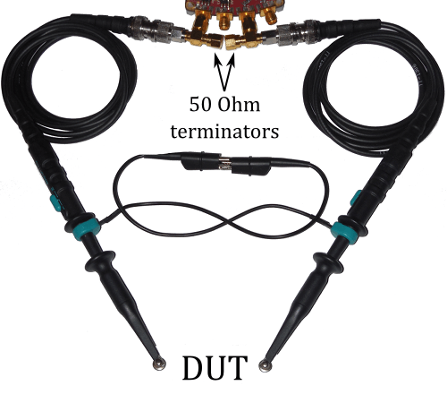
At the moment, I don't have any dedicated coupling device and I still wonder what I'm missing when using the following setup:
jadalnie klasyczne ekskluzywne meble wypoczynkowe do salonu ekskluzywne meble tapicerowane ekskluzywne meble do sypialni ekskluzywne meble włoskie
Who is online
Users browsing this forum: No registered users and 101 guests