pavel wrote:Drachenfrucht wrote:
A german documentation
is available as PDF.
Could I use the mentioned reflexion bridge for my goal?
I could not find any schematics of the bridge in the PDF document. So, I don't know how to compare it with the bridge suggested by the author of the HamVNA program.
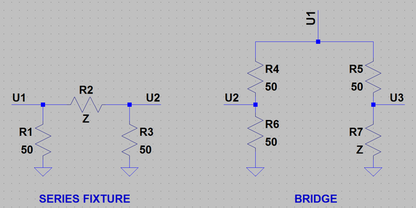
Is there any particular reason that you need the reflection bridge?
The series fixture is easier to build (just a few resistors) and even the author of the HamVNA program writes that he uses the series fixture more often because it works both in the transmission and reflection modes.
I've just tried two scope probes as a series fixture. Using my RX antenna as a DUT I could see some resonances. Unfortunately, I don't have any reference antenna analyzer or VNA to compare with.
Hi again,
as we already said, I won't focus on HamVNA any more but instead I will focus on your application called "VNA". I want to ask again you or Gregg related to the reflexion bridge I am using:
fa_reflexionsmesskopf.jpg
THIS IS THE PDF for that reflection bridge in german. I am not good in translating but I will give a try to explain what this manual says about this reflection bridge:
For reflection measurements with the Network Analyzer a measuring head is needed that provides a sharpness of directivity more than 35dB at the range from 0,1 to 160MHz and at 160MHz this sharpness of directivity should be at least 30dB. Such a unit as described here is needed for measuring passive elements like antennas, filters at the load of 50 Ohm (usual values are SWR, return loss, etc.). Criteria of quality for the measurement accuracy is the return loss, also known as sharpness of directivity. This value shows how much power is reflected unwanted even on a matched impedance -here 50 Ohm-.
This reflection bridge measuring head consists of a
special coupler called TDC-10-1 manufactured by Mini Circuits. As already mentioned it provides a very good sharpness of directivity better than 30dB which is quite enough for the ham radio world. The following table shows the directivity attenuation, reflection factor and minimum displayable SWR:
table.jpg
This is how the reflection bridge looks like inside:
reflection_bridge_1.jpg
reflection_bridge_2.jpg
The following illustration shows how the reflection bridge is connected to the VNA board:
reflection_bridge_connection.jpg
I connected it exactly like that. The text with red colour "Zx (Messobjekt)" is the DUT.
In the following the PDF shows some results of measurements and discuss several parts. The network analyzer used there is not the RedPitaya.
So I run your VNA application on my RP and start the VNA client on my windows PC. On the right side of that reflection bridge (=where you plug the DUT) I disconnect everything and in VNA client I click on "OPEN". Then I short circuit this ende with a piece of wire and then in VNA client I click on "Short". Then I remove this short circuit wire and I insert a 50Ohm resistor into that jack and in VNA client I click on "Load". That looks like that:
On
that link you see the three screens in that order OPEN - SHORT - LOAD
But when I plug in my current balun into the DUT jack and in VNA client clicking on DUT I get this picture here:

I cannot understand that, why do I get such a result? I want to add that on the end of my current balun I have attached a 50 Ohm resistor so the impedance is matched. This 50 Ohm simulates an antenna.
Any help appreciated.