It looks like you are using the raw data with your own FPGA
I have also encountered the problem, and I have added the FPGA code from the original Red Pitaya FPGA
viewtopic.php?f=14&t=1473&p=5406#p5406
Here is the forum post with my query, the FPGA filter works very well to counteract this problem
https://github.com/RedPitaya/red-pitaya ... a_dfilt1.v#
The filter module can be found here The module is called "red_pitaya_dfilt1"
Input Stage Imperfections
-
luigiraffaele124
- Posts: 12
- Joined: Sun May 29, 2016 5:26 pm
Re: Input Stage Imperfections
I have connected OUT2 generator (with sinusoid of 0,9V @ 1kHz) to IN2 scope, with a T-connection and a 50 Ohm load.
The scope visualization is
https://www.dropbox.com/s/zm3w6vsf99tpg ... s.jpg?dl=0
We have a difference of 0,9V - 0,84V = 0,06 in peak value (that equals to an error of 20*log(0,9/0,84) = 0,6dB.
At 500Hz, 3kHz, 10kHz frequebcy, I have about the same situation.
Dont'you think that 0,6dB in an error too high at this frequency?
-
luigiraffaele124
- Posts: 12
- Joined: Sun May 29, 2016 5:26 pm
Re: Input Stage Imperfections
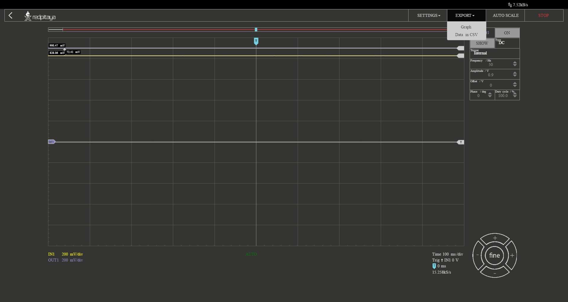
I have also tried a configuration with the generator sending a DC signal to a cable connected to the scope, with T connector and 50 Ohm termination.
The generator is sending a 900 mV signal but the scope is reading a 828 mV signal, so with 72 mV of difference.
Is this a normal behavior?
Does it depend on imperfection on low pass filter or other input stage component?
Or my board can be defective?
The generator is sending a 900 mV signal but the scope is reading a 828 mV signal, so with 72 mV of difference.
Is this a normal behavior?
Does it depend on imperfection on low pass filter or other input stage component?
Or my board can be defective?
-
redpitaya

- Site Admin
- Posts: 926
- Joined: Wed Mar 26, 2014 7:04 pm
Re: Input Stage Imperfections
Hi,
Probably in this cases (amplitude difference) board is not calibrated.
With calibrated board if you set OUT1 to 900mV
connected to IN1 (using 50OHM termination) you should get on IN1 = 900mV +- 0.5mV
Kind Regards, Zumy
Probably in this cases (amplitude difference) board is not calibrated.
With calibrated board if you set OUT1 to 900mV
connected to IN1 (using 50OHM termination) you should get on IN1 = 900mV +- 0.5mV
Kind Regards, Zumy
jadalnie klasyczne ekskluzywne meble wypoczynkowe do salonu ekskluzywne meble tapicerowane ekskluzywne meble do sypialni ekskluzywne meble włoskie
Who is online
Users browsing this forum: No registered users and 13 guests